Haltech Platinum Pro Plug-in Auxiliary Harness (HT040003)
Racepak IQ3 Display Dash (250-DS-IQ3)
The Haltech Platinum Pro Plug-in and the Racepak IQ3 Display Dash is a great combination to modernize the electronics of one's car as well as enhance one's interior. Some individuals will mount the display dash in front of the factory instrument panel. I chose to eliminate the factory instrument panel entirely. The result is a cleaner look in my opinion, but because the dash can only display what the engine control unit (ECU) outputs (unless additional components are installed), I lost the ability to track a couple crucial parameters. The purpose of this post is to demonstrate how one can display fuel level on their new dash by modifying the factory fuel tank gauge unit.
 |
| The IQ3 Display Dash mounted in the location of the factory instrument panel. |
The fuel tank gauge unit utilizes a float connected to a potentiometer. When the tank is full, the float is at the top of the slide, causing a lower resistance. As the tank empties, the float moves down a slide, increasing the resistance. As per Ohm's law, there is an inverse relationship between resistance and current. Therefore, when there is maximum current flowing through the circuit, the indicator will point to full. When there is the minimum current flowing through the circuit, the indicator will point to empty.

The instructions for the fuel tank gauge unit removal is provided below. The majority of the steps have been taken directly off the factory service manual (FSM) unless otherwise stated.

WARNING:
*Do not smoke while servicing fuel system. Keep open flames and sparks away from work area.
*Be sure to furnish workshop with a fire extinguisher.
CAUTION:
*Always replace clamps with new ones.
*Do not kink or twist tubes when they are being installed.
*Do not tighten hose clamps excessively to avoid damaging hoses.
*After installing tubes, run engine and check for fuel leaks at connections.
1. Release fuel pressure.
- Remove fuse for fuel pump.
 |
| Fuse box located to the right of the battery. |
 |
| Fuel pump fuse is rated at 15A. |
- Start engine.
- After engine stalls, crank engine two or three times to make sure that fuel pressure is released.
- Turn ignition switch off and install fuse for fuel pump.
2. Disconnect battery ground cable.
3. Remove inspection hole cover located behind the rear seat.
4. Disconnect harness connectors and fuel tubes on upper plate (put mating marks on tubes for correct installation). |
| Not an ideal way to connect the battery ground cable but the Optima RedTop is significantly taller than factory battery. However, it has not caused any issues yet. The battery ground cable is fastened by a 10mm nut. |
 |
| If the car is not stripped, there will be a metal panel (not shown) that blocks access from the cabin that must be removed. |
 |
| Inspection hole cover is fastened by 4 10mm bolts at each corner. |
 |
| The rear bolts are more easily accessed through the trunk. Again if the car is not stripped, there will be a metal panel (not shown) blocking access that must be removed. |
 |
| The restricted access coupled with the age can make these extremely difficult to remove. Use a twisting motion to break the seal. |
*This is to be done with a special service tool (KV999G0010 - fuel tank lock ring socket). Alternatively, it can be removed by jamming a screwdriver into one of the notches and hammering it.
 |
| Unfortunately, the screwdriver will deform the plastic but I could not figure out another way to remove it without the tool. |
 |
| There is 1 fuel tube and 2 harness connectors. |
 |
| In hindsight, it may have been better to do this when the fuel tank was almost empty. |

 |
| The long prong of the metal fuel pump bracket goes into the right gap of the white plastic bracket. |
*An additional harness connector must be unclipped. An easier alternative is to pull the white fuel tank gauge unit bracket upward.
 |
| The function of this harness is unknown. The other end is somewhere within the fuel tank itself. |
 |
| Take care not to bend the bracket. |
 |
| Back of the fuel tank gauge unit and bracket. |

 |
| The ledge that stops the metal bracket from sliding off. |
 |
| Place the zip ties so that it will not slide down over time due to bumps. |
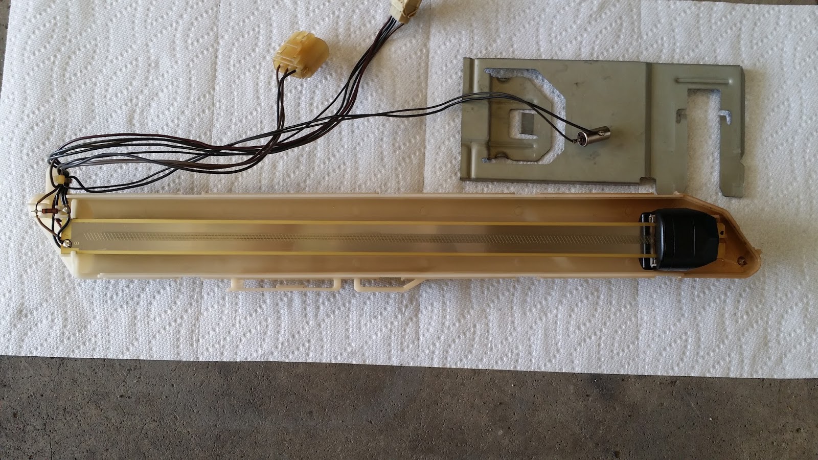 |
| The metal cylinder is the fuel level warning sensor. In this setup, it is no longer needed but take care not to damage it. |
Because the Platinum Pro is a plug and play unit, the ECU does not accommodate any additional inputs on it's own. However, the auxiliary harness can increase the function of the ECU, with the addition of an analogue voltage input (AVI) which accepts variable voltage inputs from 0-5V. This is the range in which the fuel tank gauge unit must be recalibrated. The following schematic is used. Using a breadboard to wire the capacitor and resistors will ensure a clean install (The Basics of Breadboarding).
 |
| C1 = 1000 uF, R1 = 22 000 Ω/2%, R2 = 100 Ω/2% |
 |
| The orientation of the picture is identical to the wiring diagram.The bottom right yellow wire is spliced into terminal 1 of the fuel tank gauge unit harness. |
 |
| Terminal 1 (signal) is a gray/red wire. |
Once the voltage values have been determined for an empty, half, and a full tank (refer to float position above), enter "Main Setup" by pressing the F4 key. Under "Inputs", check mark the "AVI" and set as "Fuel Level Senso"r. This will bring up a new tab called "Fuel Level" on top of the main setup page.
 |
| The relevant settings are boxed in red. |
 |
| "Insert Column" is boxed in red. One can then highlight the volts and L underneath and enter the values. |
1. Go online with your ECU.
2. Save your map, call it whatever you like. Go to FILE and then SAVE AS.
3. At the top of the screen select TOOLS and then UPGRADE FIRMWARE
4. Go to your Haltech / Firmware directory. Depending on your operating system you may need to start from My Documents to find this directory.
5. You should see a list of compatible firmware files. It will only show you versions that you can use. eg. If you have a Platinum Sport 1000 you will not see Sprint 500 files.
6. Select the latest file version.
7. You will then see the software jump back to the opening logo screen, with ERASING on the bottom left of the window. After a short time it will show progress increasing from 0 to 100%.
8. If promted, select UPGRADE. This upgraded file will be discarded in step 9. When everything is complete, power off the ECU and unplug the 34-pin connector (larger connector). Power back on the ECU.
9. UPLOAD the latest Default Base file that matches your ECU. Select FILE and then UPLOAD and then choose the matching Default Base File to the new firmware version you have used. This will be located in the "Haltech / ECU Maps / Base Maps" folder. For example, if you have a PS1000 and have upgraded to 1.09.2, and you are using VE for tuning, you would select the file named "Sport_1000-109_default_VE.hs1-109".
10. When complete you need to IMPORT your previous saved map. Select FILE and then IMPORT and select your saved map. When promted, tick all three boxes for Tables, Calibrations, Settings.
11. After you have completed importing your saved map, power off, re-connect the 34-pin connector, and power back on. You are ready to go with the latest firmware!
12. Check absolutely all settings and tables to make sure all values are as expected before attempting to start or drive the vehicle.
The reasons for doing some of these steps.
* 34-pin connector unplugging: this is done to prevent inputs or outputs falsely activating while we upload the base map. Not doing this step could cause injector or ignition output problems.
* Uploading the new Default Base Map: This is done to ensure all new functions and features that come with an update have basic values in them. Because it may be using new or different sections of memory inside the ECU, it may have random numbers present in the map. Loading the base file ensures that normal numbers are in place.
* Importing your saved map: This returns the ecu back to the same tune state as it was before the update
When you are done, check all maps and settings for normal predicted values.
Finally, make sure you're using the latest 4.2.1 version of RacePak DataLink. Copy the canparm file into your C:\Program Files (x86)\DataLinkII\Can directory, overwriting the existing file. When you run DataLinkII, fuel level will now be the last sensor to choose from in your available sensors list.
 |
| Right click an unused EFI input in the right box which will bring up "VNET Input Channel Parameters". In the sensor dropdown list, fuel level will be the last sensor to choose from. Do not alter "Vnet ID". |

Firmware update instructions and canparm file provided courtesy of HaltechMatthew and HaltechMitch, respectively. Special thanks to Adam Peeling at Haltech for troubleshooting the CAN connection issue and providing the updated firmware file.
Revival Question: Where can I get that instrument panel insert for the Haltech cluster?
ReplyDeleteNice Blog, Thank you for your this blog. Keep it up Float level sensor
ReplyDelete