Quick start guide
MAC boost control solenoid (35A-AAA-DDEA-1BA)
Product page
Application, installation, and service precautions
Catalog pages
The Haltech Platinum Pro engine control unit (ECU) is equipped with an onboard manifold absolute pressure (MAP) sensor rated to 22 psi. For forced induction applications, this is an essential metric to keep track of. Not only is it an invaluable diagnostic tool, it can be used to determine who is alpha out of your group of friends.
On an RB26 with an individual throttle body setup, the line must be connected after the throttle bodies in order to measure vacuum along with pressure. Vacuum is used in a whole host of automotive processes and the ability to measure it will give you an additional tool for troubleshooting if needed. Vacuum is dependent on engine load and throttle position but essentially, the piston acts as an air pump producing suction. To my knowledge, there is only one fitting that Nissan provides which is located behind the number 3 throttle chamber.

Once the piping is completed, open the ECU manager software. Enter the F4 key on your keyboard which will bring up the "Main Setup". On the left hand side under "Inputs", check the "OBPS" and set to "Manifold Pressure Sensor 1". On the left hand side under "Basic", check that the "Primary MAP Sensor" is set to "Manifold Pressure Sensor 1". You are now ready!

As the wastegate valve opens, the exhaust is able to bypass the turbine, reducing the speed of the compressor. When the wastegate valve closes, the exhaust must go through the turbine, increasing the speed of the compressor. In practice, this happens in a continuous spectrum where it is either partially open or closed. The movement of this valve is controlled by an actuator mounted on the turbo.
[video of wastegate valve opening and closing - coming soon]
The wrapped boost line above is connected to the intake manifold through the BCS. When boost begins to build, the pressure will depress a spring which in turn will move the actuator rod, opening the wastegate valve. In a twin turbo setup, the force required to depress the spring must be identical in both wastegates. Otherwise, the boost pressure generated by the two turbos will be different leading to turbulent airflow and premature wear among a host of other issues. This can be tested using a hand pump.
There are multiple ways to set up a BCS. The method that I opted for is a 3 way normally open setup.
Port number 3 is piped into intake manifold. Port number 2 is piped into the wastegate actuators. Port number 1 is vented into the atmosphere. With a twin turbo setup, the line from port 2 will need to be split to feed both the actuators.
When the wastegate is de-energized, the boost pressure at the manifold and the boost pressure at the wastegate is identical. In order to build boost however, the engine control unit will begin to energize the solenoid as the crankshaft revolutions per minute (RPM) increases. This is referred to as duty cycle. As the duty cycle increases, the solenoid will begin to bleed the boost pressure from the wastegate, lowering the force exerted on the spring. This reduction in force acts to close the wastegate valve, forcing a greater percentage of the exhaust to go through the turbine and thus, building boost.
The tune currently on my car uses open loop boost control. This is a very simple setup where the duty cycle is predetermined based off RPM.
This method of piping is inherently safe because if the BCS fails, the boost pressure will be self regulated through a negative feedback loop. As boost pressure increases, the more the wastegate valve will open reducing the speed of the compressor and thus, boost pressure.
There are two wires for the BCS. The Haltech ECU utilizes the factory BCS harness negating the need to use an additional digital pulsed output signal. The harness is located right beside the fuse box in the engine bay. The blue/yellow is the signal wire to the ECU and the green is power through the ignition switch. It does not matter which wire is spliced into which as there is no polarity on the MAC BCS wires.
After wiring, a test can be done to determine whether or not the BCS is functional. In the appropriate software, set the duty cycle to a percentage of your choice with the RPM at 0. A ticking sound will be heard once the changes are applied. Remember to revert back to the original settings.
I realize there was far more miscellaneous content than the actual install itself but it's always good to know how things work, even if it's just for the sake of knowing.
MAC boost control solenoid (35A-AAA-DDEA-1BA)
Product page
Application, installation, and service precautions
Catalog pages
The Haltech Platinum Pro engine control unit (ECU) is equipped with an onboard manifold absolute pressure (MAP) sensor rated to 22 psi. For forced induction applications, this is an essential metric to keep track of. Not only is it an invaluable diagnostic tool, it can be used to determine who is alpha out of your group of friends.
 |
| A barbed fitting can be seen on the bottom right corner of the ECU. |

 |
| The fitting highlighted in red. |
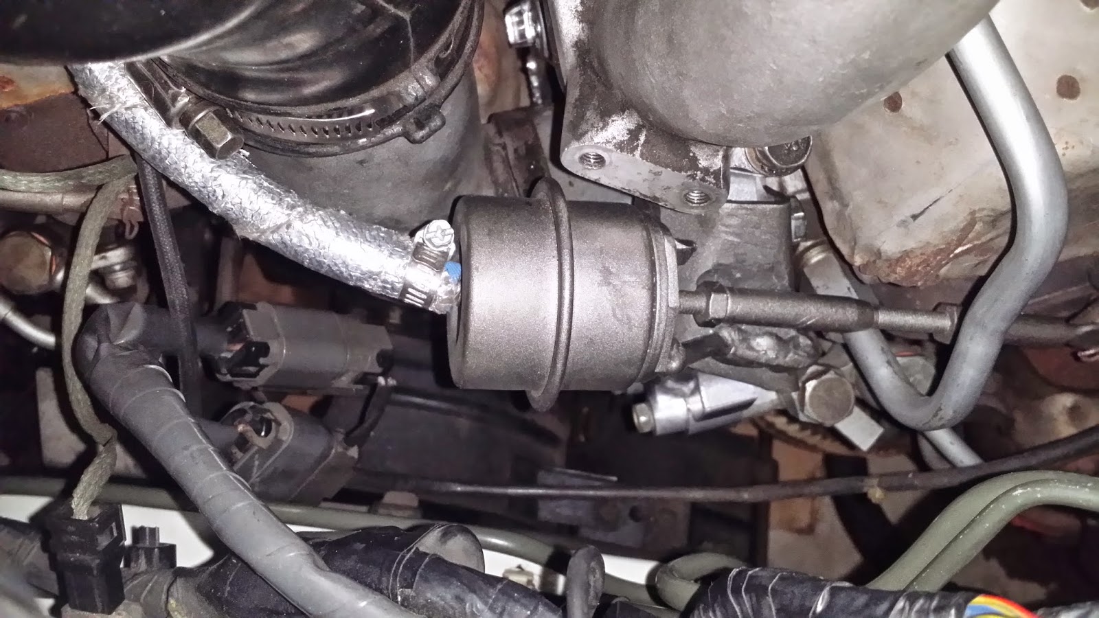
 |
| The fitting with the line attached. |

 |
| The relevant settings are boxed in red. |
The purpose of a boost control solenoid (BCS) is to regulate compressed air (referred to as boost) that is being generated by a turbocharger. This is done by controlling the extent to which the wastegate valve opens in the turbine housing. This setup, where the valve is located within the turbine housing, is referred to as an internal wastegate. How turbochargers work.
 |
| The turbine (left) and the wastegate valve (right) can be seen in this R33 GT-R stock turbocharger. |
[video of wastegate valve opening and closing - coming soon]
 |
| The wastegate actuator and the actuator rod. |
 |
| blue arrows represent boost pressure, green represents the diaphragm, orange represents the spring. |
There are multiple ways to set up a BCS. The method that I opted for is a 3 way normally open setup.
 |
| Other setups can be found in the catalog page. |
 |
| The upper port corresponds to #1, the middle port corresponds to #3, and the lower port corresponds to #2. |
When the wastegate is de-energized, the boost pressure at the manifold and the boost pressure at the wastegate is identical. In order to build boost however, the engine control unit will begin to energize the solenoid as the crankshaft revolutions per minute (RPM) increases. This is referred to as duty cycle. As the duty cycle increases, the solenoid will begin to bleed the boost pressure from the wastegate, lowering the force exerted on the spring. This reduction in force acts to close the wastegate valve, forcing a greater percentage of the exhaust to go through the turbine and thus, building boost.
The tune currently on my car uses open loop boost control. This is a very simple setup where the duty cycle is predetermined based off RPM.
 |
| The actual values must be determined by your tuner on a dynamometer. |
There are two wires for the BCS. The Haltech ECU utilizes the factory BCS harness negating the need to use an additional digital pulsed output signal. The harness is located right beside the fuse box in the engine bay. The blue/yellow is the signal wire to the ECU and the green is power through the ignition switch. It does not matter which wire is spliced into which as there is no polarity on the MAC BCS wires.
 |
| The yellow in the blue/yellow wire and the green wire both looks white due to overexposure. |
I realize there was far more miscellaneous content than the actual install itself but it's always good to know how things work, even if it's just for the sake of knowing.
No comments:
Post a Comment